For the common emitter circuit shown below (see figure 1) the parameters are:
VBB = 4 V, RB = 220 kΩ, RC = 2 kΩ, VCC = 10 V, VBE(on) = 0.7 V, and β = 200. Calculate the base current (IB), collector current (IC), emitter currents (IE), the VCE voltage and the transistor power dissipation (PT). Show all work.
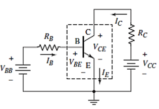
Figure 1
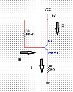
Figure 2
3. For the circuit shown in Figure 3 below, draw the DC load line and locate its quiescent or DC working point. Show all work.
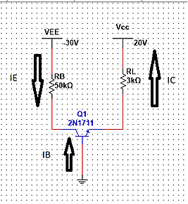
Figure 3
4. The data sheet entry that lists how much the power rating of a device has to be reduced is the__________________.
5. In a common-emitter circuit, once the base current has been calculated, collector current can be determined by multiplying the base current by ________.
**PLEASE SEE ATTACHMENT FOR FIGURES**


Delivering a high-quality product at a reasonable price is not enough anymore.
That’s why we have developed 5 beneficial guarantees that will make your experience with our service enjoyable, easy, and safe.
You have to be 100% sure of the quality of your product to give a money-back guarantee. This describes us perfectly. Make sure that this guarantee is totally transparent.
Read moreEach paper is composed from scratch, according to your instructions. It is then checked by our plagiarism-detection software. There is no gap where plagiarism could squeeze in.
Read moreThanks to our free revisions, there is no way for you to be unsatisfied. We will work on your paper until you are completely happy with the result.
Read moreYour email is safe, as we store it according to international data protection rules. Your bank details are secure, as we use only reliable payment systems.
Read moreBy sending us your money, you buy the service we provide. Check out our terms and conditions if you prefer business talks to be laid out in official language.
Read more